Welcome to the official website of Ava Espikoo Sanat

1 July ,2025 09:09

Ava Espikoo, a pioneer in the field of industrial equipment and chemicals

July 1, 2025

09:09

In industrial projects, technical, economic, and implementation aspects are first examined through a feasibility study (FS). After approval, the basic design phase begins and documents called Basic Documents are prepared. These documents include drawings and lists such as PFD, P&ID, UFD, equipment list, layout plan, control philosophy, etc., which are the basis for decision-making for detailed design and project implementation. These documents define the relationship between engineering departments and play an important role in reducing errors, costs, and project execution time.

مدارک مهندسی p & id

FS (Feasibility Study)

Feasibility Study (FS) is one of the basic and primary documents in the construction cycle of any industrial project, the purpose of which is to examine the technical, economic, financial, and environmental aspects of project implementation. This study determines whether the implementation of the desired project is feasible and cost-effective from various perspectives.

This document examines the following:

  • Market analysis: assessing demand, competitors, and sales opportunities

  • Technical assessment: Review of processes, technology, production capacity, and infrastructure

  • Financial analysis: estimating investment costs, profitability, rate of return on investment (IRR)

  • Risks and challenges: Assessment of economic, political, operational risks

  • Implementation suggestions: project implementation path, phasing, macro scheduling

The FS study is usually prepared before entering the Basic Engineering phase and plays a very important role in the decision-making of investors and managers. This document should be comprehensive, realistic, and reliable to provide a foundation for the next stages of design, financing, and implementation.

✅ Complete list of Basic Documents

CertificaterowDescription
1PFD (Process Flow Diagram) shows the flow path of materials and main equipment in the process
2UFD (Utility Flow Diagram) shows utility flows such as steam, air, water, fuel
3P&ID (Piping & Instrumentation) Piping and instrumentation diagram with valve, transmitter and line details
4PSID (Process Safety Interlock) Safety diagram and interlock logic for emergency stop or safe control
5Control PhilosophyExplanation of how to control processes, operating modes, control systems (PLC, DCS, etc.)
6Instrumentation Philosophy: Approach to instrument design and how to install, maintain, calibrate
7Layout (Plot Plan) A map of the layout of equipment, routes, buildings, and site infrastructure.
8Cause & Effect MatrixA table of relationships between causes (signals) and logical system responses
9Equipment List List of all process equipment with general specifications
10Line List List of piping lines with size, material, pressure and service
11Data Sheets Technical data sheets and design information for equipment and precision instruments
12Material Selection Report: Report on selecting suitable materials for corrosion, pressure, temperature and environment
13Hazardous Area Classification Categorizing hazardous areas for selecting explosion-proof equipment
14Utility Consumption Summary Utility Consumption Summary for Backup System Design

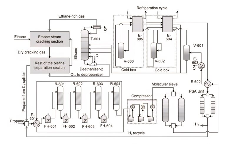
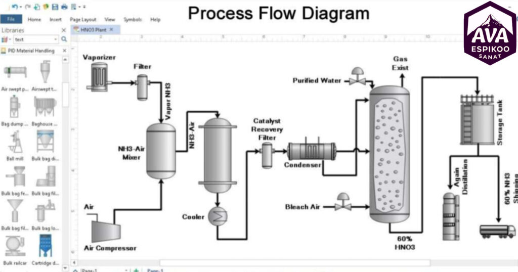
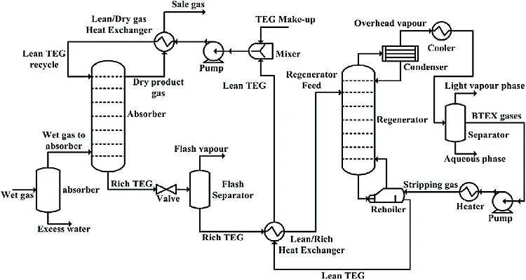
Process Flow Diagram (PFD)

PFD or Process Flow Diagram is one of the most important engineering documents in the design and analysis of process units. This diagram shows a schematic view of the main stages of an industrial process and usually includes major equipment, material flow paths, pipelines, and key operational information such as pressure and temperature at various points in the system. The main purpose of preparing a PFD is to provide an overview and understandable view of the overall process flow, without going into the details of the mechanical or piping design. In this map, components such as reactors, heat exchangers, towers, pumps, and compressors are identified with standard symbols.

The PFD is the basis for preparing other important documents such as P&IDs and safety or operational analyses. In the early phases of a project, process engineers use PFDs for performance analysis, equipment selection, and capacity estimation. Overall, the process flow map is a key tool for communication between engineering, operations, and client teams and plays an important role in the successful design and implementation of industrial projects.

InShot ۲۰۲۵۰۶۳۰ ۱۲۳۳۱۳۶۵۷

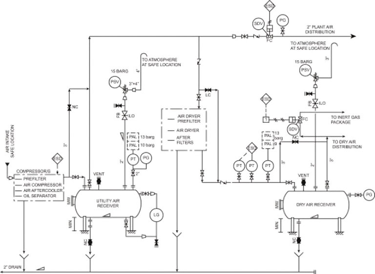
Energy Flow Map (UFD)

UFD or Utility Flow Diagram is one of the basic engineering documents in industrial projects that is used to display the paths and consumption of auxiliary services or utilities in a process unit. This map shows where auxiliary fluids such as steam, cooling water, compressed air, nitrogen, fuel gas, and other energy sources enter the system and how they are distributed or consumed.

Unlike PFD, which addresses the flow of process materials, UFD focuses on the flow of energy and ancillary services that are essential to the operation of the unit. The UFD usually displays the main equipment, utility piping network, flow, pressure, and temperature values, and resource return paths.

The UFD is prepared during the early design stages and helps engineers accurately estimate the energy needs of each part of the unit. This map is also very important for designing energy supply systems, optimizing consumption, safety, and maintenance.

Overall, UFD is an essential map for understanding how energy and services are distributed in an industrial complex and plays an important role in design, implementation, and operation.

Click the edit button to change this text. Lorem Ipsum is a fabricated text with an unintelligible simplicity produced by the printing industry and used by graphic designers.

UFD

Piping and Instrumentation Diagram (P&ID)

The term P&ID stands for Piping and Instrumentation Diagram, and in Persian it is called a piping and instrumentation diagram.

A P&ID, or Piping and Instrumentation Diagram, is an engineering diagram that shows the layout of process equipment, piping, and instrumentation in an industrial unit.
This diagram shows how components such as pumps, valves, tanks, sensors, and controllers are connected.
P&ID plays a key role in the design, operation, and maintenance of industrial units.
It also helps improve the safety and efficiency of process systems.

P&ID

Process Protection and Interlocks Map (PSID)

The PSID or Process Safety Interlock Diagram is one of the key documents in process safety engineering, used to display protective systems, interlocks (safety locks) and their sequence of operation in industrial units. This map identifies which equipment should be shut down or isolated and what actions should be taken automatically in critical situations or outside safe limits.

In PSID, sensors, alarms, safety switches, automatic valves, and other control devices that play a protective role are displayed in a graphical and standardized manner, along with their operating logic (e.g., AND, OR). These documents are usually prepared based on information contained in P&IDs and HAZOP studies.

The purpose of preparing a PSID is to prevent accidents, control operational risks, and maintain the safety of employees and equipment. This map is usually prepared during the detailed design phases of projects and also plays an important role in safety and technical review committees.

Overall, the PSID complements documents such as the PFD and P&ID and provides a clear view of the system’s safety mechanisms.

Technical Data Sheet

A data sheet is one of the most important engineering documents in the design, purchase, and manufacture of industrial equipment. This document provides all the technical information, performance specifications, and design requirements of a specific piece of equipment in a precise and standardized manner. Each process equipment such as a pump, heat exchanger, valve, compressor, tank, or precision instrument has its own datasheet. This sheet includes information such as operating pressure and temperature, component material, connection type, capacity, voltage, design standards, and special requirements.

Datasheets are usually prepared by process or mechanical engineers during the basic or detailed design phase and are the basis for preparing manufacturer proposals and selecting suppliers. This document is also used as a reference during the construction, testing, and commissioning of the equipment and is retained in the final project documentation. Overall, the Data Sheet is a key tool for ensuring that equipment meets process requirements, meets safety and quality standards, and reduces errors in project execution stages.

Cause & Effect Matrix

The Cause and Effect Matrix is ​​one of the important tools in process control and safety engineering that is used to display the relationship between alarm or fault conditions (causes) and associated control or protective actions (disabilities). In this matrix, the rows usually contain causes such as pressure, temperature, flow, or equipment errors, and the columns contain responses such as safety valve activation, pump shutdown, or emergency system stop. The intersection houses determine what reaction each cause leads to.

This tool is widely used in the design of ESD (Shutdown Systems) and SIS (Safety Instrumented Systems) systems and plays an important role in safety analysis and automated response to critical conditions. Also, the cause and effect matrix is ​​usually prepared based on the results of studies such as HAZOP or LOPA.

Overall, the Cause & Effect Matrix is ​​an important reference for control, instrumentation, and safety engineers to ensure the proper functioning of systems in the face of errors and to prevent potential hazards.

Line List و Equipment List

Line List and Equipment List are two key documents in industrial projects that provide detailed information about pipelines and process equipment to engineering, purchasing, construction, and installation teams.

Line List (list of pipelines)

The Line List contains complete specifications for each pipeline in the process unit. Information such as:

  • Line Number

  • Fluid inside the tube

  • Diameter, thickness, pressure and design temperature

  • Pipe material

  • Thermal or refrigeration insulation

  • Flange class and design code

This list is the primary reference for piping design, material selection, and pipeline implementation.

Equipment List

This list includes all the main equipment of the unit such as pumps, tanks, converters, reactors, compressors, etc. Each row usually includes:

  • Equipment number and name

  • Type

  • Capacity

  • Working pressure and temperature

  • Equipment service or use

  • Location and relevant map

Layout map

Layout drawings are one of the most important engineering documents in the design of industrial units, which graphically display the exact location of equipment, buildings, piping routes, cables, and access routes. This map is usually presented in the form of a two-dimensional (2D) or three-dimensional (3D) map. The purpose of preparing a layout is to ensure spatial coordination between various components, compliance with safety principles, easy access for repairs and operation, and optimal use of space on the project site. This plan is usually started in the Basic Design phase and updated and completed in the Detail Design phase.

Layout includes the placement of major equipment such as tanks, pumps, exchangers, pipe runs, ladders, stairways, power lines, and safety systems such as emergency escape routes. It also includes standards such as minimum distance between equipment, prevailing wind direction, crane access, and safety requirements.

Ultimately, the layout map is a key tool for engineering, construction, safety, and operations teams, helping to reduce errors and accelerate project execution.

Instrumentation in Box

The term Instrumentation in Box refers to a collection of instrumentation equipment that is centrally installed and wired within a specific box or enclosure (usually metal or fiberglass). These boxes are used in industrial projects for local control and monitoring of processes. These boxes house components such as pressure, temperature, level transmitters, valve positioners, switches, terminal blocks, and digital or analog displays. The purpose of using Instrumentation in Box is to protect instrumentation equipment from environmental conditions (humidity, dust, heat, or corrosion) and to centralize wiring and make repairs easier.

These boxes are usually installed near equipment such as tanks, pumps or converters and are connected to a central control system or DCS. Boxes can be designed as local panels or relay boxes and have protection standards such as IP65 or explosion-proof (ATEX/EX). Overall, Instrumentation in Box is a reliable, standardized, and effective solution for maintaining and accurately connecting precision instrumentation equipment in industrial units.

Control Philosophy

Control Philosophy is a basic document in the design of control systems and industrial automation that specifies the general framework for how processes are controlled and operated. This document explains the project engineering perspective on how processes are monitored, regulated, and secured.

This document usually covers the following:

  • Introduction to control systems: Such as DCS, PLC, ESD and F&G

  • Control strategies for key equipment

  • Control type (automatic or manual) in different conditions

  • How the system responds to alarms and errors

  • Prioritizing emergency shutdown or isolation

  • The philosophy of alarms, signaling and interlocks

  • Communication between different units and upstream or downstream systems

This document is prepared in the early stages of project design and is the basis for preparing other documents such as P&ID, Cause & Effect, and controller programming. Having a clear and precise Control Philosophy allows for better coordination between engineering, operations, and safety teams.

Features of Ava Espikoo Sanat in preparing engineering documents

  • High accuracy in design and technical calculations

  • Full compliance with international standards and codes

  • Identifying and mitigating potential project risks

  • Preparing complete, accurate documents

  • Increasing speed and coordination between project teams

  • Reduce rework and correction costs

Communication methods

AVA ESPIKOO SANAT

Ava Espikoo Sanat Company is known as one of the pioneers of the industrial field in Iran with a brilliant history and deep expertise in the oil, gas, petrochemical and energy industries. At Ava Espikoo Sanat, relying on advanced technical knowledge and a committed team, we offer comprehensive and diverse solutions in the fields of design, construction and operation of large industrial projects.

Our location

All rights to this site belong to Ava Espikoo Sanat.